- 您现在的位置:买卖IC网 > Sheet目录180 > 2866242 (Phoenix Contact)UPS 24VDC 40A DIN RAIL
�� �
�
�Uninterruptible� Power� Supply� Unit� for� Universal� Use� –� QUINT-DC-UPS/24DC/40�
�5.6.� Output�
�All� devices� that� must� be� supplied� without� interruption�
�in� the� event� of� a� supply� voltage� failure�
�("Buffered� Load"),� are� connected� to� the� "Output� +"� and�
�"Output� -"� terminal� blocks� of� the� DC� output� (Fig.� 08).� It�
�is� recommended� that� all� other� loads,� which� do� not�
�require� buffering� ("Unbuffered� Load"),� are� connected� to�
�40�
�35�
�30�
�25�
�20�
�15�
�12 Ah�
�7.2 Ah�
�3.4 Ah�
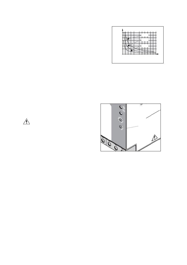
�the� 24� V� DC� output� of� the� power� supply.�
�This� increases� the� buffer� time,� as� this� time� depends�
�on� the� output� current� (see� Fig.� 10).� The� internal� diode�
�ensures� that� the� buffered� loads� are� isolated� from� the�
�unbuffered� loads.�
�10�
�5�
�0�
�30�
�60�
�Time� [min.]�
�90�
�120�
�Figure� 10�
�5.7.� Battery� Module�
�The� battery� module� is� connected� to� the�
�40�
�+� t� t�
�at.� M�
�-C� od�
�ha� e�
�rg�
�we�
�OK�
�[m� ax� 0,5� 1�
�Ba�
�ele� 0�
�[A� t�
�tte�
�rvic�
�≤� 3�
�≥� 1� ,2�
�od�
�at.� -M� h� arge�
�t.-�
�Ba� OK�
�er�
�Po�
�PR�
�U�
�ST�
�EQ� KA�
�QUINT-DC-UPS� via� the� "Battery� +"� and� "Battery� -"�
�terminal� blocks.� To� interrupt� the� charge/discharge�
�current� of� the� battery� module,� the� "Battery� module�
�selection"� selector� switch� $� must� be� set� to� "Service".�
�The� fuse� on� the� battery� module�
�must� be� removed� when� installing� or�
�replacing� the� battery� module.�
�The� QUINT-DC-UPS� is� optimized� for� use� with�
�QUINT-BAT/24DC� type� battery� modules.�
�The� following� battery� modules� are� recommended:�
�QUINT-BAT/24DC/3,4AH� (Order� No.� 2866349)�
�V�
�u�
�O� A�
�pu�
�–�
�e�
�Po�
�r� In�
�t�
�m�
�in]� ∞�
�30�
�t.-S� 2�
�c�
�h]�
�Ba�
�+�
�2�
�3�
�5�
�15� 10�
�Se�
�7�
�2�
�ry�
�e�
�,4�
�B� C�
�w�
�In�
�e�
�$�
�AP�
�LI�
�O�
�ED�
�IN� NT�
�CO� UIP�
�43�
�R�
�be�
�QUINT-BAT/24DC/7,2AH� (Order� No.� 2866352)�
�QUINT-BAT/24DC/12AH� (Order� No.� 2866365)�
�When� using� QUINT-BAT/24DC/3,4AH,� the� maximum�
�output� current� of� 25� A� must� not� be� exceeded.�
�Following� successful� installation,� the� capacity� of� the�
�connected� battery� module� must� be� selected� using� the�
�"Battery� module� selection"� rotary� switch� $� .�
�5.8.� Signaling� Outputs�
�The� signal� outputs� are� connected� via� terminal� blocks�
�11/12/13� 4� ,� 21/22/23� 5� or� 31/32/33� 6� .� The� contacts�
�are� ?� oating� contacts.� The� plug-in� bridge� provided� can�
�be� used� to� supply� +24� V� to� grouped� contacts� 11,21,31.�
�This� means� that� N/C� contacts� 12,22,32� and� N/O�
�contacts� 13,23,33� can� be� evaluated� as� switching�
�outputs� with� 0� V� and� +24� V� voltage� levels.�
�PHOENIX� CONTACT� page� 7� of� 9�
�–�
�Figure� 11�
�发布紧急采购,3分钟左右您将得到回复。
相关PDF资料
2866255
PWR SUPPLY 5A 100-240AC 48VDC
2866297
PWR SUPPLY 8A 100-240AC 10-15VDC
2866336
PWR SUPPLY 100W 100-240AC 24VDC
2866446
POWER SUPPLY 1.3A 100-240AC 24DC
2866640
UPS 24VDC 2A
2866653
POWER SUPPLY 1.5A 24VDC
2866679
POWER SUPPLY 5A 85-264AC 48DC
2866682
POWER SUPPLY 10A 48VDC
相关代理商/技术参数
28-6625-10
功能描述:IC 与器件插座 DIP HEADERS 28 PINS SCREW MACHINE CONT RoHS:否 制造商:Molex 产品:LGA Sockets 节距:1.02 mm 排数: 位置/触点数量:2011 触点电镀:Gold 安装风格:SMD/SMT 端接类型:Solder 插座/封装类型:LGA 2011 工作温度范围:- 40 C to + 100 C
28-6625-11
功能描述:IC 与器件插座 DIP HEADERS 28 PINS SCREW MACHINE CONT RoHS:否 制造商:Molex 产品:LGA Sockets 节距:1.02 mm 排数: 位置/触点数量:2011 触点电镀:Gold 安装风格:SMD/SMT 端接类型:Solder 插座/封装类型:LGA 2011 工作温度范围:- 40 C to + 100 C
28-6625-20
功能描述:IC 与器件插座 DIP HEADERS 28 PINS SCREW MACHINE CONT RoHS:否 制造商:Molex 产品:LGA Sockets 节距:1.02 mm 排数: 位置/触点数量:2011 触点电镀:Gold 安装风格:SMD/SMT 端接类型:Solder 插座/封装类型:LGA 2011 工作温度范围:- 40 C to + 100 C
28-6625-21
功能描述:IC 与器件插座 DIP HDR 28P GLD RoHS:否 制造商:Molex 产品:LGA Sockets 节距:1.02 mm 排数: 位置/触点数量:2011 触点电镀:Gold 安装风格:SMD/SMT 端接类型:Solder 插座/封装类型:LGA 2011 工作温度范围:- 40 C to + 100 C
28-6625-31
功能描述:IC 与器件插座 DIP HEADERS 28 PINS SCREW MACHINE CONT RoHS:否 制造商:Molex 产品:LGA Sockets 节距:1.02 mm 排数: 位置/触点数量:2011 触点电镀:Gold 安装风格:SMD/SMT 端接类型:Solder 插座/封装类型:LGA 2011 工作温度范围:- 40 C to + 100 C
2866255
功能描述:DIN导轨式电源 POWER SUP 48VDC 5A
RoHS:否 制造商:Mean Well 产品:Linear Supplies 商用/医用:Commercial 输出功率额定值:960 W 输入电压:180 VAC to 264 VAC, 254 VDC to 370 VDC 输出端数量:1 输出电压(通道 1):48 V 输出电流(通道 1): 输出电压(通道 2): 输出电流(通道 2): 输出电压(通道 3): 输出电流(通道 3): 尺寸:150 mm L x 110 mm W